HYE-QUE Antenna Connector Specifications
The Budwig HQ-1 Antenna connector is for use by ham radio operators and others in fabricating an inexpensive and efficient dipole antenna. Designed for durability and light weight, this connector provides a coax SO-239 socket for accepting PL-259 feed line plug. The one piece molded body offers weather tight construction and provides a drip shield to protect the coax fittings. Full legal power capacity.
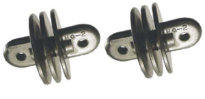
The Budwig HQ-2 Antenna Insulator is designed for use with Budwig HQ-1 Connector when constructing a dipole antenna assembly. Deep ribbed construction provides increased surface path to reduce power leakage. Light weight and durable.
Material: ABS Copolymer, 20% Glass filled
Stock Colors: Green (Olive Drab)
Parts are Conflict Minerals 3TG Compliant.
HQ – 1


HQ – 2


- Refer to Wire Length Table, select the frequency within the band in which you usually operate. Cut two wires, each to the length indicated. Make a right angle bend exactly three inches from both ends of both wires. If you propose to operate the entire band, cut both wires to the length indicated for the approximate center of the band.
- Insert one three inch end of one of the antenna wire into one end hole of the connector as shown in Figure 1, twist this three inch end around wires A and B as shown in Figures 1 and 2.
- Repeat with the other antenna wire at the opposite end hole of the connector.
- Hold pliers at C in Figure 2 and solder at D.
- Attach insulators at the other three inch ends of the antenna wires, solder, using pliers as a heat sink as before.
- Attach a PL-259 plug to the coax cable, affix the plug to the connector.
- If desired, the connector may be used to make an “Inverted Vee” antenna. Shorten the wires by 6%, use the top hole in the connector to support the antenna. The low antenna ends should be at least eight feet off the ground.
- Two or more additional antenna wires, cut for additional bands may also be attached to the connector as previously outlined. These additional antenna wires may be at an angle to the other wires, or droop slightly under them, but they must not touch.
- In all cases, the coax feeder line must be at least as long as one of the longest antenna wires used. Refer to Wire Length Table.
| SPECIFICATIONS | ||
| Material: ABS 20% Glass Fiber Filled | ||
| PROPERTIES | A.S.T.M. TEST METHOD | |
| Tensile Strength | 18,000 psi | D638-D651 |
| Compressive Strength | 30,000 psi | D695 |
| Flexural Strength | 34,000 psi | D790 |
| Dielectric Strength | 500-600V | D149 |
| Dielectric Constant at 60Hz | 2.1 | D150 |
| Dielectric Constant at 10³Hz | 2.1 | D150 |
| Dielectric Constant at 10 Hz | 2.1 | D150 |
| Dielectric Constant at 10 Hz | .0003 | D150 |
| Effect of Sunlight | NIL | D150 |
| Effect of Weather | NIL | — |
| Service Life | Indefinite | — |
| Internal Capacity | NIL | — |
Wire Lengths for 1/2 Wave Dipole Antenna
To determine the correct Di-Pole Antenna WIRE LENGTHS visit the On-Line and Downloadable CALCULATORS located at any of the web sites below:
www.csgnetwork.com/antennaedcalc.html
www.hamuniverse.com/dipivcal.html
www.radiobrandy.com/dipole1.html


